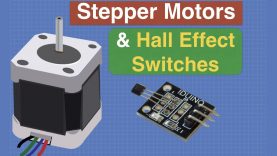
Control a Stepper Motor with Hall Effect Switches
After we learn how Hall Effect switches work, we’ll use them to build limit switches and homing sensors for stepper motors.
Article with code samples – https://dbot.ws/hallsw
More tutorials and projects – https://dronebotworkshop.com
Get involved in the forum – https://forum.dronebotworkshop.com
Sign up for the newsletter – https://dbot.ws/dbnews
More code on GitHub – https://dbot.ws/github
Today we will learn about Hall Effect sensors and switches.
These devices are sensitive to magnetism and can be put to use in a number of interesting applications. Hall Effect switches are inexpensive and are very easy to use, with or without an Arduino.
After we do a few simple experiments we will see how to control a stepper motor using Hall Effect switches and an Arduino. We will look at two common arrangements:
Limit Switches – Controlling the end of travel of the motor, or of the mechanism being powered by the motor.
Homing Sensor – Having the motor or mechanism move to a predetermined position on command.
The hookup and code for all of the experiments is very simple, and if you don’t want to use Hall Effect switches you can substitute other switches instead.
In my experiment, I used a NEMA-17 size stepper, an A4988 stepper motor driver and a 12-volt power supply. But you could easily adapt the design to use any stepper motor, driver and power supply combination.
Here is what is covered in today’s video:
How Hall Effect switches work – 4:24
Simple Hall Effect experiments – 7:08
Simple Arduino experiment – 10:24
Build a Limit Switch – 14:19
Build a Homing Sensor – 22:59
If you need more information or want a closer look at the code you’ll find an article at https://dbot.ws/hallsw that accompanies this video.
Hope you enjoy the video and that it gives you some ideas for implementing Hall Effect sensors and switches into your own projects.
source

