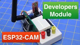
Build an ESP32-CAM Developers Module with Power Supply
This easy-to-build Developers Module simplifies working with the ESP32-CAM and also provides a useful portable power supply for all your experiments.
Article with schematics on the website: https://dbot.ws/esp32mod
More articles and tutorials: https://dronebotworkshop.com
Join the conversation on the forum: https://forum.dronebotworkshop.com
Subscribe to the newsletter and stay in touch: https://dbot.ws/dbnews
Today I’m building a project, an ESP32-CAM Developers Module. This handy contraption allows me to easily work with and program an ESP32-CAM module, without all the tangle of wires usually involved. It also provides a portable power supply that allows me to use the ESP32-CAM just about anywhere, and it even eliminates the dreaded “Blackout” condition messages!
I actually built this while filming another ESP32-CAM video, which you’ll be seeing soon. I love the inexpensive ESP32-CAM module, but experimenting with it presents a number of difficulties:
– The Reset switch is on the BOTTOM of the module, meaning you have no access to it on a solderless breadboard. And you need to have access to it.
– Even if you do get it onto a breadboard it eats up a lot of the pins. There is only space left for one connection to each module pin.
– You need to ground the GPIO IO0 pin when programming the module.
– Speaking of programming, you need an external FTDI adapter to program the module, or to use the serial monitor.
– If you don’t have enough current to get the radio started for Bluetooth or WiFi you’ll receive a “Brownout” error message. This is not unique to the “CAM” module, it’s an issue with most ESP32 modules.
– If you add an external antenna it becomes even more awkward to experiment with this module.
I ended up building this little project, which I’m presenting to you as a useful way of working with the ESP32-CAM.
Here is the Table of Contents for today’s video:
00:00 – Introduction
03:48 – ESP32-CAM Prototyping Issues
06:40 – Development Module Features
13:51 – Module Parts Required
18:50 – Module Schematic
24:43 – Module Construction
30:50 – Building the Power Supply Base
37:58 – Testing the Power Supply
40:13 – Testing the Developers Module
Even if you don’t build this exact project you can still use the same concept for other microcontrollers that you work with frequently. Or you can make a better one with a bigger breadboard and more LEDs and pushbuttons.
And the power supply would be a useful project in its own right, it is both battery and AC adapter powered and it provides 3.3 and 5 volts in a very comp[act and easy-to-build unit.
Hope you enjoy it, and if you like the ESP32-CAM please subscribe – I’ll be doing a lot more with it now that I have my developers module!
source
